What data recovery tools to buy if you want to start a data recovery business?
Free video data recovery training on how to recover lost data from different hard drives?
Where to buy head and platter replacement tools at good prices?
Data recover case studies step by step guide
I want to attend professional data recovery training courses
The flash file systems on USB memory sticks are usually relatively simple mechanisms that only translate the Logical Block Number used in high level file systems to a low level physical address and do not support wear levelling. In the file systems described in this chapter, the block size of the flash file system is equal to the erase block size of the flash memory chip used. This means that when a logical block changes, the new version is stored in a new erase block and the complete oldversioniserased.This is not a very efficient way of dealing with flash memory, because pages within an erase block that are not changed are still copied to the new block and the old page is erased, yielding a higher wear that absolutely necessary for this block.
In the USB memory sticks studied for this chapter, the concept of zones is used in two devices . In these devices, a zone is defined as a group of erase blocks, for example: 1024 erase blocks are grouped into a zone. Within this zone, 1000 blocks are actively used to store the high level file system, 24 blocks are kept aside to replace bad blocks when they arise. These blocks are marked in a special way, so that they can be recognised by the controller as such.
For the study on which this section is based a reference collection of USB memory sticks was needed. To create this collection, colleagues at the NFI were asked whether they owned any USB memory and whether they wanted to trade
it for a new 128 Mbyte device. This resulted in 45 sticks of different make and model.
Identification of controller and memory chips
The controller chips found in USB sticks are sometimes hard to identify, mainly because often only a manufacturer logo and a part number can be found on the chip. But even with this information and some creative Internet queries the manufacturer of the controller can be identified. The memory chips are often much easier to identify. The memory chip usually carries the manufacturer name and logo and the part number. Furthermore, contrary to controller chips, flash chips appear to be produced by companies well known in the electronics industry.
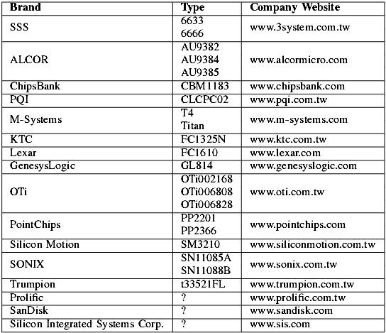
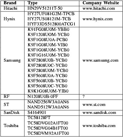
In the reference collection of 45 USB memory sticks, 16 different manufacturers of controllers have been identified, who produced 24 different controllers. Table IV shows all controllers identified in the reference collection. In the reference collection, 8 different manufacturers of NAND flash memory have been identified, who produced 26 different types of chips. Table V shows all unique memory chips identified in the reference collection. To put the number of different memory chips in perspective, most NAND flash memory chips are compatible but some important properties are differing. Some of these properties are:
* Storage capacity: 16 Mbyte to 128 Mbyte
* Number of addressing cycles: three, four or five
* Width of the I/O bus: 8 or 16 bit
* Operating voltages: 1.70~1.95V, 2.4~2.9V, 2.7~3.6V
* Erase block size: 16 kbyte, 128 kbyte
* Page size: 528 byte, 2112 byte
* Housing: TSOP 48
TABLE IV
CONTROLLER CHIPS IDENTIFIED IN THE REFERENCE COLLECTION
TABLE V
NAND FLASH CHIPS, IDENTIFIED IN THE REFERENCE COLLECTION
Data recovery Salon welcomes your comments and share with us your ideas, suggestions and experience. Data recovery salon is dedicated in sharing the most useful data recovery information with our users and only if you are good at data recovery or related knowledge, please kindly drop us an email and we will publish your article here. We need to make data recovery Salon to be the most professional and free data recovery E-book online.



Comments are closed
Sorry, but you cannot leave a comment for this post.